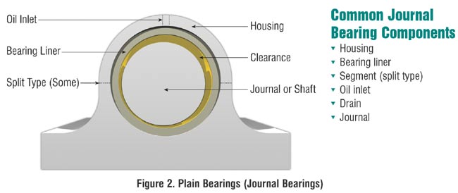
Journal or plain bearings consist of a shaft or journal which rotates freely in a supporting metal sleeve or shell. There are no rolling elements in these bearings. Their design and construction may be relatively simple, but the theory and operation of these bearings can be complex. This article concentrates on oil- and grease-lubricated full fluid film journal bearings; but first a brief discussion of pins and bushings, dry and semilubricated journal bearings, and tilting-pad bearings.
Low-speed pins and bushings are a form of journal bearing in which the shaft or shell generally does not make a full rotation. The partial rotation at low speed, before typically reversing direction, does not allow for the formation of a full fluid film and thus metal-to-metal contact does occur within the bearing. Pins and bushings continually operate in the boundary lubrication regime. These types of bearings are typically lubricated with an extreme pressure (EP) grease to aid in supporting the load. Solid molybdenum disulfide (moly) is included in the grease to enhance the load-carrying capability of the lubricant. Many outdoor construction and mining equipment applications incorporate pins and bushings. Consequently, shock loading and water and dirt contamination are often major factors in their lubrication.
Dry journal bearings consist of a shaft rotating in a dry sleeve, usually a polymer, which may be blended with solids such as molybdenum, graphite, PTFE or nylon. These bearings are limited to low-load and low-surface speed applications. Semilubricated journal bearings consist of a shaft rotating in a porous metal sleeve of sintered bronze or aluminum in which lubricating oil is contained within the pores of the porous metal. These bearings are restricted to low loads, low-to-medium velocity and temperatures up to 100°C (210°F).
Tilting-pad or pivoting-shoe bearings consist of a shaft rotating within a shell made up of curved pads. Each pad is able to pivot independently and align with the curvature of the shaft. A diagram of a tilt-pad bearing is presented in Figure 1. The advantage of this design is the more accurate alignment of the supporting shell to the rotating shaft and the increase in shaft stability which is obtained.1 An article on tilting-pad bearings appeared in the March–April 2004 issue of Machinery Lubrication magazine.

Figure 1. Kingsbury Radial
and Thrust Pad Bearing
Journal bearings are meant to include sleeve, plain, shell and babbitt bearings. The term babbitt actually refers to the layers of softer metals (lead, tin and copper) which form the metal contact surface of the bearing shell. These softer metals overlay a stronger steel support shell and are needed to cushion the shell from the harder rotating shaft.
Simple shell-type journal bearings accept only radial loading, perpendicular to the shaft, generally due to the downward weight or load of the shaft. Thrust or axial loads, along the axis of the shaft, can also be accommodated by journal bearings designed for this purpose. Figure 1 shows a tilt-pad bearing capable of accepting both radial and thrust loads.

Figure 2. Layers of Journal Bearing Structure
Journal bearings operate in the boundary regime (metal-to-metal contact) only during the startup and shutdown of the equipment when the rotational speed of the shaft (journal) is insufficient to create an oil film. It is during startup and shutdown when almost all of the damage to the bearing occurs.2 Information on plain bearing failures was discussed in an article in the July – August 2004 issue of ML magazine. Hydrostatic lift, created by an external pressurized oil feed, may be employed to float large, heavy journals prior to startup (shaft rotation) to prevent this type of damage. During normal operation, the shaft rotates at sufficient speed to force oil between the conforming curved surfaces of the shaft and shell, thus creating an oil wedge and a hydrodynamic oil film. This full hydrodynamic fluid film allows these bearings to support extremely heavy loads and operate at high rotational speeds. Surface speeds of 175 to 250 meters/second (30,000 to 50,000 feet/minute) are common. Temperatures are often limited by the lubricant used, as the lead and tin babbitt is capable of temperatures reaching 150°C (300°F).
It is important to understand that the rotating shaft is not centered in the bearing shell during normal operation. This offset distance is referred to as the eccentricity of the bearing and creates a unique location for the minimum oil film thickness, as illustrated in Figure 3.

Figure 3. Shaft Motion During Startup
Normally, the minimum oil film thickness is also the dynamic operating clearance of the bearing. Knowledge of the oil film thickness or dynamic clearances is also useful in determining filtration and metal surface finish requirements. Typically, minimum oil film thicknesses in the load zone during operation ranges from 1.0 to 300 microns, but values of 5 to 75 microns are more common in midsized industrial equipment. The film thickness will be greater in equipment which has a larger diameter shaft. Persons requiring a more exact value should seek information on the Sommerfeld Number and the Reynolds Number. Discussion of these calculations in greater detail is beyond the scope of this article. Note that these values are significantly larger than the one-micron values encountered in rolling element bearings.
The pressures encountered in the contact area of journal bearings are significantly less than those generated in rolling bearings. This is due to the larger contact area created by the conforming (similar curvature) surfaces of the journal and the shell. The mean pressure in the load zone of a journal bearing is determined by the force per unit area or in this case, the weight or load supported by the bearing divided by the approximate load area of the bearing (the bearing diameter times the length of the bearing). In most industrial applications, these values range from 690 to 2,070 kPa (100 to 300 psi). At these low pressures, there is virtually no increase in the oil viscosity in the bearing contact area due to pressure. Automotive reciprocating engine bearings and some severely loaded industrial applications may have mean pressures of 20.7 to 35 MPa (3,000 to 5,000 psi). At these pressure levels, the viscosity may slightly increase. The maximum pressure encountered by the bearing is typically about twice the mean value, to a maximum of about 70 MPa (10,000 psi).
Oil whirl is a phenomenon that can occur in high-speed journal bearings when the shaft position within the shell becomes unstable and the shaft continues to change its position during normal operation, due to the fluid forces created within the bearing. Oil whirl may be reduced by increasing the load or changing the viscosity, temperature or oil pressure in the bearing. A permanent solution may involve a new bearing with different clearances or design. Oil whip occurs when the oil whirl frequency coincides with the system’s natural frequency. The result can be a catastrophic failure.3
Oil Lubrication
Oils are used in journal bearings when cooling is required or contaminants or debris need to be flushed away from the bearing. High-speed journal bearings are always lubricated with oil rather than a grease. Oil is supplied to the bearing by either a pressurized oil pump system, an oil ring or collar or a wick. Grooves in the bearing shell are used to distribute the oil throughout the bearings’ surfaces.
The viscosity grade required is dependent upon bearing RPM, oil temperature and load. The bearing speed is often measured strictly by the revolutions per minute of the shaft, with no consideration of the surface speed of the shaft, as per the “ndm” values calculated for rolling bearings. Table 1 provides a general guideline to selecting the correct ISO viscosity grade.
The ISO grade number indicated is the preferred grade for speed and temperature range. ISO 68- and 100-grade oils are commonly used in indoor, heated applications, with 32-grade oils being used for high-speed (10,000 RPM) units and some outdoor low-temperature applications. Note in the table that the higher the bearing speed, the lower the oil viscosity required; and that the higher the operating temperature of the unit, the higher the oil viscosity that is required. If vibration or minor shock loading is possible, a higher grade of oil than the one indicated in Table 1 should be considered.
| Bearing Speed |
Bearing / Oil Temperature (°C)
|
|||
| (rpm) |
0 to 50
|
60
|
75
|
90
|
| 300 to 1,500 |
–
|
68
|
100 to 150
|
–
|
| ~1,800 |
32
|
32 to 46
|
68 to 100
|
100
|
| ~3,600 |
32
|
32
|
46 to 68
|
68 to 100
|
| ~10,000 |
32
|
32
|
32
|
32 to 46
|
Table 1. Journal Bearing ISO Viscosity Grade Selection
Another method of determining the proper viscosity grade is by applying minimum and optimum viscosity criteria to a viscosity-temperature plot. A generally accepted minimum viscosity of the oil at the operating temperature for journal bearings is 13 cSt, although some designs allow for an oil as thin as 7 or 8 cSt at the operating temperature. The optimum viscosity at operating temperature is 22 to 35 cSt, for moderate-speed bearings if no shock loading occurs. The optimum viscosity may be as high as 95 cSt for low-speed, heavily loaded or shock-loaded journal bearings.
Using this method requires some knowledge of the oil temperature within the bearing under operating conditions, which can be difficult to determine. Fortunately, an accurate oil temperature is not needed for most viscosity determinations. It is common to determine the temperature of the outer surface of the pipes carrying oil to and away from the bearing. The temperature of the oil inside of the pipes will generally be higher (5 to 10°C, 10 to 18°F) than the outer metal surface of the pipe. The oil temperature within the bearing can be taken as the average of the oil entering versus the temperature exiting the bearing.4
A third and more complex method is to calculate the oil viscosity needed to obtain a satisfactory oil film thickness. Persons wishing to learn more about this method should seek information regarding the Sommerfeld equation and either eccentricity ratios or Reynolds Numbers.4
If the oil selected is too low in viscosity, heat will generate due to an insufficient film thickness and some metal-to-metal contact will occur. If the oil is too high in viscosity, heat will again be generated, but due to the internal fluid friction created within the oil. Selecting an oil which is too high in viscosity can also increase the likelihood of cavitation. The high- and low-pressure zones, which are created within the oil on each side of the area of minimum film thickness, can cause oil cavitation in these bearings. Cavitation is a result of expansion of dissolved air or a vapor (water or fuel) in the low-pressure zone of the bearing. The resulting bubble implodes, causing damage, as it passes through the high-pressure portion of the bearing. If the implosion or collapse of the vapor bubble occurs next to the metal surface, this can cause cavitation pitting damage to the metal. If the implosion of the bubble occurs within the oil, a micro hot spot or micro-dieseling can occur, which may lead to varnishing within the system.
Typically, a rust and oxidation (R&O) inhibited additive system is used in the oils employed in these applications. Antifoam and pour point depressant additives may also be present. Antiwear (AW) hydraulic oils may also be used as long as the high-temperature limit of the zinc AW component is not exceeded and excessive water is not present. R&O oils tend to have better water separation characteristics, which is beneficial, and the AW properties of a hydraulic oil would be beneficial only during startup and shutdown, assuming a properly operating bearing.
Grease Lubrication
Grease is used to lubricate journal bearings when cooling of the bearing is not a factor, typically if the bearing operates at relatively low speeds. Grease is also beneficial if shock loading occurs or if the bearing frequently starts and stops or reverses direction. Grease is almost always used to lubricate pins and bushings because it provides a thicker lubricant than oil to support static loads and to protect against vibration and shock-loading that are common in many of these applications.
Lithium soap or lithium complex thickeners are the most common thickeners used in greases and are excellent for most journal bearing applications. The grade of grease used is typically an NLGI grade #2 with a base oil viscosity of approximately 150 to 220 cSt at 40°C. Greases for low-speed, high-load, high temperatures and for pins and bushings may use a higher viscosity base oil and be formulated with EP and solid additives. Greases for improved water resistance may be formulated with heavier base oils, different thickeners and special additive formulations. Greases for better low-temperature dispensing may incorporate a lower viscosity base oil manufactured to an NLGI #1 specification. Bearings lubricated by a centralized grease dispensing systems typically use a #1, 0 or 00 grade of grease.
The apparent viscosity of grease changes with shear (pressure, load and speed) that is, greases are non-Newtonian or thixotropic. Within a rotating journal bearing, as the bearing rotates faster (shear rate increases), the apparent viscosity of the grease decreases and approaches the viscosity of the base oil used in grease. At both ends of the bearing shell, the pressure is lower and therefore the apparent viscosity remains higher. The resulting thicker grease at the bearing ends acts as a built-in seal to reduce the ingression of contaminants.
Greasing Procedures
The greasing procedures for journal bearings and pins and bushings are not as well-defined or as critical as for rolling bearings because the grease is not subjected to the churning action created by the rolling elements. The volume of grease to inject and the frequency of application are dictated more by trial and error. Generally, most journal bearings cannot be overgreased. Caution must be taken when pumping grease into a bearing that is fitted with seals, so they are not damaged or displaced by the force and volume of the incoming grease. The harshness of the environment, shock loading and especially the operating temperature will be major factors in determining the frequency of relubrication.
Journal bearings are generally a simpler design and not as difficult to lubricate as rolling element bearings. The proper viscosity matched to the operating conditions and a clean and dry lubricant will usually suffice to form a full fluid lubricating film and provide excellent bearing life.
For the latest information about bearing lubrication, begin a free subscription to Machinery Lubrication magazine.

When an element is stretched in one direction, it tends to get thinner in the other two directions. Hence, the change in longitudinal and lateral strains are opposite in nature (generally). Poisson’s ratio ν, named after Simeon Poisson, is a measure of this tendency. It is defined as the ratio of the contraction strain normal to the applied load divided by the extension strain in the direction of the applied load. Since most common materials become thinner in cross section when stretched, Poisson’s ratio for them is positive.
For a perfectly incompressible material, the Poisson’s ratio would be exactly 0.5. Most practical engineering materials have ν between 0.0 and 0.5. Cork is close to 0.0, most steels are around 0.3, and rubber is almost 0.5. A Poisson’s ratio greater than 0.5 cannot be maintained for large amounts of strain because at a certain strain the material would reach zero volume, and any further strain would give the material negative volume.

Some materials, mostly polymer foams, have a negative Poisson’s ratio; if these auxetic materials are stretched in one direction, they become thicker in perpendicular directions.Foams with negative Poisson’s ratios were produced from conventional low density open-cell polymer foams by causing the ribs of each cell to permanently protrude inward, resulting in a re-entrant structure.
An example of the practical application of a particular value of Poisson’s ratio is the cork of a wine bottle. The cork must be easily inserted and removed, yet it also must withstand the pressure from within the bottle. Rubber, with a Poisson’s ratio of 0.5, could not be used for this purpose because it would expand when compressed into the neck of the bottle and would jam. Cork, by contrast, with a Poisson’s ratio of nearly zero, is ideal in this application.

It is anticipated that re-entrant foams may be used in such applications as sponges, robust shock absorbing material, air filters and fasteners. Negative Poisson’s ratio effects can result from non-affine deformation, from certain chiral microstructures, on an atomic scale, or from structural hierarchy. Negative Poisson’s ratio materials can exhibit slow decay of stress according to Saint-Venant’s principle. Later writers have called such materials anti-rubber, auxetic (auxetics), or dilatational. These materials are an example of extreme materials.

The size of screw conveyor depends on two factors
1. The capacity of the conveyor
2. The lump size of the material to be conveyed (Maximum dimensions of the particle)
Usually there are three ranges of lump sizes which are considered for selection of screw size. These are:
· A mixture of lumps and fines in which not more than 10% are lumps ranging from maximum size to one half of the maximum, and 90% are lumps smaller than one half of the maximum size.
· A mixture of lump and fines in which not more than 25% are lumps ranging from the maximum size to one half of the maximum, and 75% are lumps smaller than one half of the maximum size.
· A mixture of lump only in which 95% or more are lumps ranging from maximum size to one half of the maximum size and 5% or less are lumps less than one tenth of the maximum size.
The allowable size of a lump in a screw conveyor is a function of the radial clearance between the outside diameter of the central pipe and the radius of the inside of the screw trough, as well as the proportion of the lumps in the mixture.
The lump size of the material affects the selection of screw diameter which should be at least 12 times larger than the lump size of a sized material and four times larger than the largest lumps of an un-sized material.
Example, if screw diameter is 250mm means radial clearance is 105mm, & Maximum lump size is 60mm of 10% lumps.
Capacity of Screw Conveyor:

The capacity of a screw conveyor depends on the screw diameter, screw pitch, speed of the screw and the loading efficiency of the cross sectional area of the screw. The capacity of a screw conveyor with a continuous screw:
Q = V. ρ
Q = 60. (π/4).D2.S.n.ψ.ρ.C
Where,
Q = capacity of a screw conveyor
V = Volumetric capacity in m3/Hr
ρ = Bulk density of the material, kg/m3
D = Nominal diameter of Screw in m
S = Screw pitch in m
N = RPM of screw
Ψ = Loading efficiency of the screw
C = Factor to take into account the inclination of the conveyor
Screw Pitch:
Commonly the screw pitch is taken equal to the diameter of the screw D. However it may range 0.75 – 1.0 times the diameter of the screw.

Loading efficiency:
The value of loading efficiency should be taken large for materials which are free flowing and non abrasive, while for materials which are not free flowing and or abrasive in nature, the value should be taken low:
Ψ = 0.12 to 0.15 for abrasive material
= 0.25 to 0.3 for mildly abrasive material
= 0.4 to 0.45 for non abrasive free flowing materials
Inclination Factor:
The inclination factor C is determined by the angle of screw conveyor with the horizontal.
| Angle of screw with the horizontal | 0° | 5° | 10° | 15° | 20° |
| Value of factor C | 1 | 0.9 | 0.8 | 0.7 | 0.65 |
Types of screw flight:
The screw of the conveyor may be right hand or left hand, the right hand type being the usual design. The threads of the screw may be single, double or triple.
The flight of the screws may be made in either of the two ways:
1. As Helicoids
2. As Sectional flight
Helicoids Flight:
They are formed from a flat bar or strip into a continues helix. The threads are thinner at the outer edge and thicker at the inner edge.

Sectional flights:
Sectional flights are formed from a flat disc and the thickness of the thread is uniform throughout. A continuous helix is made by joining a number of sectional flights together on a piece of pipe and butt welded them. Various styles of screw flights are in use, depending on the service required.

Some of the typical configurations are:
1. Short pitch or continuous flight:
If the conveyor is required to handle dry granular or powdered materials that do not pack, this style of flight may be selected. It is of regular construction and recommended for inclined conveyors having a slope of 20 or more, including vertical conveyors. This style is extensively used as feeder screw.
2. Ribbon flight:
If the conveyor is to handle lumpy, clinging, sticky, gummy or viscous substances, this type flight may be selected. It consists of continuous helical flight formed from steel bar and secured to the pipe by supporting lugs.

3. Cut flight:
In this type of flight screws have notches cut in the periphery of the flight. These notches supplement the conveying with moderate mixing action. They are recommended for conveyors required to handle light, fine, granular or flaky materials.

4. Cut and folded flights:
This type of flight is characterized by notches as in cut flight, together with folded segments. This type of flight creates agitation and aeration resulting in better mixing. This type of flight is used to handle light or medium weight materials having fine, granular or flaky materials.
5. Some screw conveyors have cut flight with paddles mounted at regular intervals. The paddles counteract the flow of material past the flight resulting in greater agitation and mixing.
6. Sometimes screws are made of stainless steel to suit special requirements, like the sanitation requirements for handling food, drugs and other hygienic materials.
Further, the hydrogen engine ensures performance and reliability equal to that of a gasoline engine. Since the gasoline version requires only a few design changes to allow it to operate on hydrogen, hydrogen-fueled rotary engine vehicles can be realized at low cost. In addition, because the dual-fuel system allows the engine to run on both hydrogen and gasoline, it is highly convenient for long-distance journeys and trips to areas with no hydrogen fuel supply.
 technology-electronic controlled gas injection-EGR (Exhaust Gas Recirculation)-Dual Fuel system")
Technology of the RENESIS Hydrogen Rotary Engine:
The RENESIS hydrogen rotary engine employs direct injection, with electronically-controlled hydrogen gas injectors. This system draws in air from a side port and injects hydrogen directly into the intake chamber with an electronically-controlled hydrogen gas injector installed on the top of the rotor housing. The technology illustrated below takes full advantage of the benefits of the rotary engine in achieving hydrogen combustion.

RE Features suited to Hydrogen Combustion
In the practical application of hydrogen internal combustion engines, avoidance of so-called backfiring (premature ignition) is a major issue. Backfiring is ignition caused by the fuel coming in contact with hot engine parts during the intake process. In reciprocal engines, the intake, compression, combustion and exhaust processes take place in the same location—within the cylinders. As a result, the ignition plugs and exhaust valves reach a high temperature due to the heat of combustion and the intake process becomes prone to backfiring.
In contrast, the RE structure has no intake and exhaust valves, and the low-temperature intake chamber and high-temperature combustion chamber are separated. This allows good combustion and helps avoid backfiring.
Further, the RE encourages thorough mixing of hydrogen and air since the flow of the air-fuel mixture is stronger and the duration of the intake process is longer than in reciprocal engines.

Combined use of Direct Injection and Premixing
Aiming to achieve a high output in hydrogen fuel mode, a direct injection system is applied by installing an electronically-controlled hydrogen gas injector on the top of the rotor housing. Structurally, the RE has considerable freedom of injector layout, so it is well suited to direct injection.
Further, a gas injector for premixing is installed on the intake pipe enabling the combined use of direct injection and premixing, depending on driving conditions. This produces optimal hydrogen combustion.
When in the gasoline fuel mode, fuel is supplied from the same gasoline injector as in the standard gasoline engine.
Adoption of Lean Burn and EGR
Lean burn and exhaust gas recirculation (EGR) are adopted to reduce nitrogen oxide (NOx) emissions. NOx is primarily reduced by lean burn at low engine speeds, and by EGR and a three-way catalyst at high engine speeds. The three-way catalyst is the same as the system used with the standard gasoline engine.
Optimal and appropriate use of lean burn and EGR satisfies both goals of high output and low emissions. The volume of NOx emissions is about 90 percent reduced from the 2005 reference level.

Dual Fuel System
When the system runs out of hydrogen fuel, it automatically switches to gasoline fuel. For increased convenience, the driver can also manually shift the fuel from hydrogen to gasoline at the touch of a button.


The Standing Task Chair is the worlds first device for ergonomically supporting the human body in a standing position. It reduces the fatigue of prolonged standing by removing the weight of your body from your legs, while at the same time positioning your body so that you can be effective at performing tasks that require standing.

YOGA INSPIRED BODY POSITIONING: The Standing Task Chair is unique in the way it positions your body. The inspiration comes from a Yoga standing meditation pose. In Yoga, they teach you to be aware of your relationship with gravity, so that you stay upright with a minimum of physical effort and focus on aligning your bones with gravity, to make it is as easy as possible to relax your muscles. The Standing Task Chair uses the same body positioning and adds support at the seat, knees and feet. Your upper body is aligned with gravity in the same manner so that your body naturally conforms to a more healthy, comfortable position.
EFFECTIVE FOR COMPLEX TASKS: Tasks that we normally do standing require us to have the ability to move, to reach and to apply forces.
The Standing Task Chair works effectively at these complex tasks because it positions your body so that you can apply forces like downward pressure, pushing and pulling. It allows you to step from side to side without getting off the chair and gives you leverage to reach for objects.

LEVERAGE FOR APPLYING FORCES: The unique combination of the angled foot platform and the knee pad gives your body leverage and control so that you can effectively apply forces necessary for standing tasks.
ERGONOMIC SUPPORT:The fatigue of prolonged standing is reduced by removing the weight of your body from your legs and distributing your weight over your seat, knees and feet.
IMPROVED SPINE ALIGNMENT: Sitting is not a natural position for the spine. The standing position takes the stress off your back so you can spend hours performing standing tasks without fatigue.

DESIGNED FOR STANDING HEIGHT WORK SURFACES: Kitchen Counters, Benches, Standing Desks, Table Saws, Cash Registers, Copy Machines, Drafting Tables, Audio Mixing Boards. These are just a few of the work surfaces at which we typically stand to perform tasks.
FREEDOM OF MOVEMENT: The seat pivots from the base to allow it to move when you move. You can step from side to side and turn your body while the seat follows your motion. The Standing Task Chair gives you the same freedom of movement that you have when you’re standing on your feet, while reducing leg and foot fatigue.
FLEXIBLE AND ADJUSTABLE:With the height-adjustable kneepad and the seat on a gas spring, the Standing Task Chair can be adjusted for us by almost everyone, regardless of their height and weight.

MOVING THE CHAIR: To move the chair, you pick it up by the seat, which activates the wheels, move it where you want it, and set it down. The chair is designed to remain stationary when in use.
BUILT WITH THE FINEST MATERIALS: Only the finest materials are used in the construction of the Standing Task Chair. The frame is made of solid oak, or welded steel,and powder coated The knee pad is made with high density foam and the contoured gel filled seat gives you hours of comfort.
PRODUCTION PLAN: We plan to make two versions of the STC in the beginning, one with a solid oak base as in our prototype and one with a welded steel base. Functionality will be the same. The steel base version will be finished with a black powder coating.
Although most of the parts will be purchased off the shelf, a few will have to be custom made and dies produced. The money from Kickstarter will be spent streamlining the design for mass production and having dies made for the custom parts and ordering raw materials to fulfill orders . Assembly, packaging and shipping will be done at our assembly plant in Winnsboro Texas.
There are always risks when bringing a new product to market.But we already have our own facility for assembly, packaging and shipping.The seat, gas cylinder and pivot are off the shelf products.The wood base pieces will be processed at a CNC manufacturer then brought into our facilities for assembly.The steel frame will be welded and powder coated at a local manufacturer and sent to our assembly plant.Fabrication of the connecting pieces will require dies to be made.
The funds raised from this Kickstarter project will be used to create that tooling and produce the first production run (100 to 1,000 units). We conservatively estimate 4-6 months from beginning tooling to first production run completion.
The biggest risk with Kickstarter is that you don’t know if we will have to build 80 chairs or 8000. We are set up with short run manufactures who can quickly and easily produce the smaller volumes (up to 1000).If we are highly successful, we will find manufacturers who have higher production capabilities.These are fairly simple fabrications so we don’t see any problems meeting the demand, but we have addressed the possibility of delays by spreading the estimated delivery out for higher quantities.
Source: Kickstarter
 Tesla turbine pump

Pillow block bearing

Crankshaft

Double Acting Hydraulic Cylinder

The mechanical hand

Constant speed universal joint

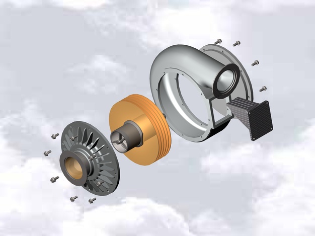
Tubocharger

Turbocharger

Slip clutch
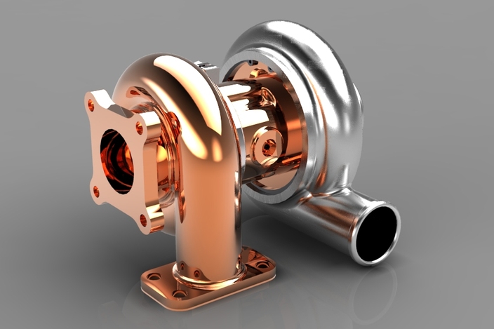
Turbocharger
Hydraulic brakes for rc cars

3/8″ 150 psi stainless steel ball valve
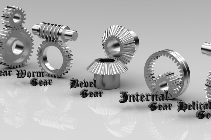
gears

Wankel rotary engine single rotor 654cc
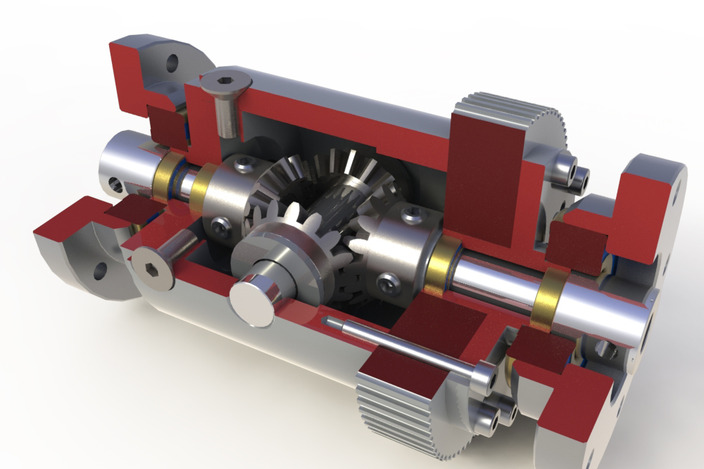
differential
 Bevel gear
Slider crank
Car suspension
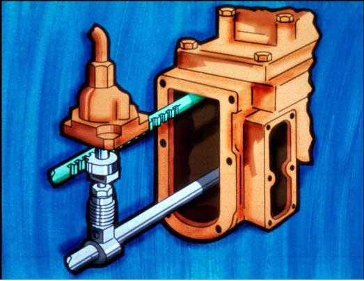
A governor is essentially a speed-sensitive device, designed to maintain a constant engine speed regardless of load variation.
To view some numerical problems on Governors, click the link below:
GOVERNORS
A governor is essentially a speed-sensitive device, designed to maintain a constant engine speed regardless of load variation. Since all governors used on diesel engines control engine speed through the regulation of the quantity of fuel delivered to the cylinders, these governors may be classified as speed-regulating governors. As with the engines themselves there are many types and variations of governors. In this module, only the common mechanical-hydraulic type governor will be reviewed.
The major function of the governor is determined by the application of the engine. In an engine that is required to come up and run at only a single speed regardless of load, the governor is called a constant-speed type governor. If the engine is manually controlled, or controlled by an outside device with engine speed being controlled over a range, the governor is called a variable speed type governor. If the engine governor is designed to keep the engine speed above a minimum and below a maximum, then the governor is a speed-limiting type. The last category of governor is the load limiting type. This type of governor limits fuel to ensure that the engine is not loaded above a specified limit. Note that many governors act to perform several of these functions simultaneously.


 WARNING Fig. 03